Help - Electrical
The Help & How To guide for MX-5 Electrics

Mk.1 - Fog/Spot Lights
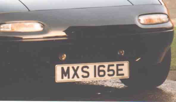
Lamps shown are Ring - Illuminator 2 fog lamps
Fitting Spot/Fog Lights - You will require the following items:
Fit the relay to the left hand side of the engine bay, (on the bonnet support securing clip bracket) there should be a threaded hole (5mm dia.). This is used for the official Mazda fog lamp relay. Feed 1 thin wire through the bulkhead, this feeds the relay coil from the On/Off Switch. The 12Volt supply needs to come from a supply isolated by the ignition switch (I wired mine from the dim/dip relay supply). The supply for the lights comes from the fuse box (L/H side rear of engine bay) via the relay. The 2 lamps are then connected in parallel to the relay (normally open contacts). See diagram below.
 |
Fog-light
Wiring Diagram.
Mk.1 - Fitting Air Horns
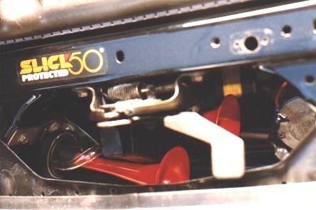
Location of Air Horns
The diagram below shows the dimensions for a suitable bracket needed to hold the air horns if one is not supplied. The short length bolts to the drivers side original horn bracket. The compressor bolts to the passenger side and connects to the original horn supply wires. The original 'STOP 10A' fuse has to be upgraded to 20Amps. This is because the original fuse will blow if you sound the air horns and apply the brakes at the same time. When installing my air horns I connected both existing horn wires together to reduces the chance of wire failure due to the high current needed by the compressor. I also fitted a 15Amp in-line fuse as extra protection, this is not essential but I would recommend it because if the compressor fails, the 15Amp fuse blows before the upgraded 20Amp 'STOP' fuse so the rear brake lights will still work.
 |
Diagram of Air Horn Bracket
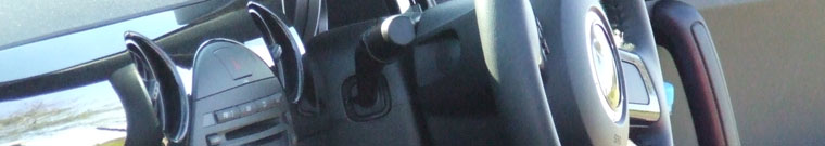
Mk.1 Side Lights instead of Dim/Dip.?
Location of Air Horns
Disconnect Dim/Dip relay connector (Connector wire colours - White/White&Blue/Black&Yellow/Red&White) or as I have done, cut the small black and yellow wire feeding the rear left hand side relay and insert a small switch in line so that the Dim/Dip System can be re-activated if required. As this wire is isolated by the ignition switch I also connected the feed to my fog lamp switch from the positive side of the switch.